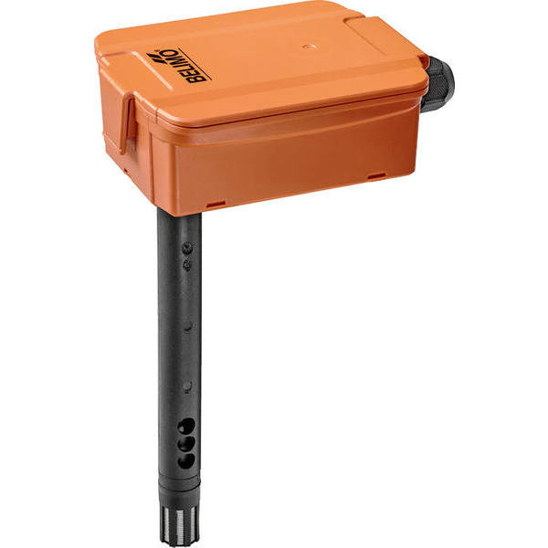
22DTC-1105
This product is no longer available. Please see our other products in this category or contact us for more info.
Duct Sensor CO₂ / Temperature active, 0…5 V, 0…10 V, Probe length 7″ [180 mm], Probe diameter 0.78″ [19.5 mm]
| Weight | 0.60 lbs |
|---|---|
| Application | Duct |
| Brand | Belimo |
| Sensor type | air quality |
| Output signal | 0…10 V, 0…5 V |
- Measuring range temperature
- 0...50°C
- Accuracy temperature active
- ±0.9°F @ 70°F [±0.5°C @ 21°C]
- Measuring range CO₂
- 0...5000 ppm
- Accuracy CO₂
- ±(50 ppm + 3% of measuring value)
- Operating condition air flow
- min. 1 ft/s [0.3 m/s]|max. 33 ft/s [10 m/s]
- Calibration
- self-calibration, Dual Channel
- Sensor Technology
- CO₂: NDIR (non dispersive infrared) dual channel
- Cable gland
- PA6, black
- Medium temperature
- 30...120°F [0...50°C]
- Ambient temperature
- 30...120°F [0...50°C]
- Output signal active temperature
- DC 0...5 V|DC 0...10 V
- Output signal active CO₂
- DC 0...5 V|DC 0...10 V
- Output signal active note
- output DC 0...5/10 V with jumper adjustable|voltage output: min. 10 kΩ load
- Probe material
- PA6, black
- Probe diameter
- 0.78" [19.5 mm]
- Probe length
- 7" [180 mm]
- Power supply DC
- 15...24 V
- Power supply tolerance DC
- ±10%
- Power consumption DC
- 1.5 W
- Power supply AC
- 24 V
- Power supply tolerance AC
- ±10%
- Power consumption AC
- 2.9 VA
- Build-up of self-heating remark
- Remark: Occurring draft leads to a better carrying-off of dissipative power at the sensor. Thus temporally limited fluctuations might occur upon temperature measurement.
- Mounting type duct
- Single Point
- Application text
- For CO₂ and temperature measurement in duct applications. Dual channel CO₂ technology with range 0...5000ppm. NEMA 4X / IP65 rated enclosure.
- Measuring values
- CO₂|temperature
- Sensor type
- air quality
- Housing type
- Duct
- Application
- Duct
- Sensor powertype
- active
- Cable entry
- Cable gland with strain relief Ø6...8 mm
- Electrical connection
- Removable spring loaded terminal block max. 2.5 mm²
- Ambient humidity
- max. 95% r.H. non-condensing
- Mounting instruction
- Mounting instruction - 71968-00001.D 22DTM-..
- Degree of protection IEC/EN
- IP65
- Certification IEC/EN
- IEC/EN 60730-1
- Certification UL
- cULus acc. to UL60730-1A/-2-9, CAN/CSA E60730-1:02/-2-9
- Protection class IEC/EN
- III safety extra-low voltage (selv)
- Protection class UL
- UL Class 2 Supply
- Quality Standard
- ISO 9001
- Material short text
- Duct CO2 5000+Temp Sensor V
- Output signal
- DC 0...5 V DC 0...10 V
- Housing
- UV resistant|cover: lexan, orange|base: lexan, orange|seal: 0467 NBR70, black
- Optional accessories
- A-22D-A06|A-22G-A01.1
- Electrical connection note
- Removable spring loaded terminal block max. 2.5 mm²
- Connection
- terminals
- Product family
- Sensor
- CAD data 3D
- Belimo_22DT..-1.._DC..-1.._3D.stp
- General remarks sensors
- Sensing devices with a transducer should always be operated in the middle of the measuring range to avoid deviations at the measuring end points. The ambient temperature of the transducer electronics should be kept constant. The transducers must be operated at a constant supply voltage (±0.2 V). When switching the supply voltage on/off, onsite power surges must be avoided.
- Information self-calibration feature CO₂
- All CO₂ sensors are subject to drift caused by the aging process of the components, resulting in regular re-calibration or replacement units. However the dual channel technology integrates automatic self-calibration technology vs common used ABC-Logic sensors. Dual channel self-calibration technology is ideally suited for applications operating 24/7 hours such as hosiptals or other commerical applications. Manual calibration is not required.
- Build-up of self-heating
- Temperature sensors with electronic components always have a dissipative power which affects the temperature measurement of the ambient air. The dissipation in active temperature sensors shows a linear increase with rising operating voltage. This dissipative power should be taken into account when measuring temperature. As Belimo transducers work with a variable operating voltage, only one operating voltage can be taken into consideration, for reasons of production engineering. Transducers 0 to 10 V / 4 to 20 mA have a standard setting at an operating voltage of DC 24 V. That means, that at this voltage, the expected measuring error of the output signal will be the least. For other operating voltages, the offset error will be increased by a changing power loss of the sensor electronics. If a re-calibration should become necessary later directly on the sensor, this can be done by means of a trimming potentiometer on the sensor board.
- General caution
- The installation and assembly of electrical equipment should only be performed by authorized personnel. This device has been designed for use in stationary heating, ventilation and air conditioning systems and must not be used outside the specified field of application. Unauthorised modifications are prohibited. The product must not be used in relation with any equipment that in case of a failure may threaten human, animals or assets. Ensure all power is disconnected before installing. Do not connect to live/operating equipment.
- Additional caution
- Please comply with • Local laws, health & safety regulations, technical standards and regulations • Condition of the device at the time of installation, to ensure safe installation • This data sheet and installation manual
Datasheet Download: Datasheet
Installation instructions Download: Installation instructions

Need Help?
Call one of our experts 1-888-423-2525
Monday-Friday EST 6:00am - 4:00pm


