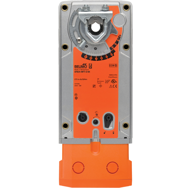
EFB24-MFT-S N4
This product is no longer available. Please see our other products in this category or contact us for more info.
Damper Actuator, 270 in-lb [30 Nm], Spring return, AC/DC 24 V, DC 2…10 V, 2 x SPDT, NEMA 4
| Weight | 12 lbs |
|---|---|
| Torque | 270 in-lb [30 Nm] |
| Brand | Belimo |
| Voltage | AC/DC 24 V |
| Auxiliary Switch | 2 SPDT |
| Actuator Type | Spring return |
| Control type | MFT/Programmable |
- Torque motor
- 270 in-lb [30 Nm]
- Power consumption in operation
- 9.5 W
- Power consumption in rest position
- 4.5 W
- Transformer sizing
- 16 VA (class 2 power source)
- Ambient humidity
- 5...95% r.H. non-condensing
- Housing material
- Aluminum die cast and plastic casing
- Electrical Connection
- Terminal block(s) inside junction box with knockouts
- Auxiliary switch
- 2 x SPDT, 3A resistive (0.5A inductive) @ 250 VAC, one set at 10°, one set at 85°
- Manual override
- 5 mm hex crank (3/16" Allen), supplied
- Angle of rotation
- Max. 95°, adjustable with mechanical end stop, 35...95°
- Position indication
- visual indicator, 0° to 95° (0° is full spring return position)
- Ambient temperature
- -22...122°F [-30...50°C]
- Non-operating temperature
- -40...176°F [-40...80°C]
- Control
- MFT/programmable
- Control operating range Y note
- 4...20 mA w/ ZG-R01 (500 Ω, 1/4 W resistor)
- Options positioning signal
- variable (VDC, PWM, on/off, floating point)
- Operating range Y variable
- Start point DC 0.5...30 V|End point DC 2.5...32 V
- Position Feedback
- DC 2...10 V, Max. 0.5 mA, VDC variable
- direction of rotation motor
- reversible with built-in switch
- Overload Protection
- electronic throughout 0° to 95° rotation
- Input Impedance
- 100 kΩ for DC 2...10 V (0.1 mA), 500 Ω for 4...20 mA, 1500 Ω for PWM, On/Off and Floating point
- Degree of Protection
- IP66, NEMA 4, UL Enclosure Type 4
- Nominal voltage
- AC/DC 24 V
- Nominal voltage frequency
- 50/60 Hz
- Power Supply
- 24 VAC, ±20%, 50/60 Hz, 24 VDC, -10% / +20%
- Power supply tolerance AC
- ±20%
- Power supply tolerance DC
- -10% / +20%
- Agency Listing
- cULus acc. to UL60730-1A/-2-14, CAN/CSA E60730-1:02, CE acc. to 2004/108/EC and 2006/95/EC
- Angle Of Rotation Adaption
- off (default)
- override control
- min. position = 0% , mid. Position = 50% , max. position = 100% (Default)
- Operating Range
- DC 2...10 V (default), 4...20 mA w/ ZG-R01 (500 Ω, 1/4 W resistor), variable (VDC, PWM, on/off, floating point)
- Emergency control function
- Spring Return
- Product family
- Damper Actuator
- direction of rotation spring-return
- reversible with cw/ccw mounting
- Noise level, motor
- ≤45.3 dB (A) @ 150 sec, run time dependent
- Shaft Diameter
- 1/2" to 1.05" round, centers on 3/4" with insert, 1.05" without insert
- Electrical accessories
- ADS-100|IRM-100|MFT-P|P475|P475-1|PS-100|PTA-250|SGA24|SGF24|UK24BAC|UK24LON|UK24MOD|ZG-R01|ZG-R02|ZG-SGF|ZG-X40|ZK1-GEN|ZK2-GEN|ZTH US
- Mechanical accessories
- AV8-25|EF-P|IND-EFB|K9-2|KG10A|KH10|KH-EFB|SH10|TOOL-07|ZG-100|ZG-120|ZG-DC1|ZG-DC2|ZG-EFB|ZG-JSA-3
- Family Series
- EF Series
- Noise Level (Fail-Safe)
- ≤71 dB (A)
- Running time (Fail-Safe)
- <20 seconds
- Running Time (Motor)
- default 150 sec, variable 60...150 sec
- Running Time (Fail-Safe)
- <20 sec @ -4...122°F [-20...50°C], <60 sec @ -22°F [-30°C]
- Fail-Safe function
- Spring return
- Control type
- MFT/Programmable
- Connection
- terminals
- Degree of protection IEC/EN
- IP66
- Degree of protection NEMA/UL
- NEMA 4
- Enclosure
- UL Enclosure Type 4
- Auxiliary Switch
- 2 SPDT
- CAD ThomasNetLink
- EFB24-MFT-S N4
- Product Features
- Torque min. 270 in-lb, for control of air dampers, Control 2 to 10 VDC (Default), Feedback 2 to 10 VDC (Default)
- Electrical Protection
- actuators are double insulated
- Operation
- The EF..24-MFT N4 actuator provides 95° of rotation and comes with a graduated position indicator showing 0° to 95°. The actuator will synchronize the 0° mechanical stop or the physical damper mechanical stop and use this as its zero position during normal control operations. A unique manual override allows the setting of any actuator position within its 95° of rotation with no power applied. This mechanism can be released physically by the use of a crank supplied with the actuator. When power is applied the manual override is released and the actuator drives toward the fail-safe position. The actuator uses a brushless DC motor which is controlled by an Application Specific Integrated Circuit (ASIC) and a microprocessor. The microprocessor controls the ASIC to provide a constant rotation rate and to know the actuator’s exact position. The ASIC monitors and controls the brushless DC motor’s rotation and provides a Digital Rotation Sensing (DRS) function to prevent damage to the actuator in a stall condition. The position feedback signal is generated without the need for mechanical feedback potentiometers using DRS. The actuator may be stalled anywhere in its normal rotation without the need of mechanical end switches. The EF..24-MFT N4 is mounted directly to control shafts up to 1.05" diameter with its universal clamp and anti-rotation bracket. A crank arm and several mounting brackets are available for damper applications where the actuator cannot be direct coupled to the damper shaft. The spring return system provides minimum specified torque to the application during a power interruption. The EF..24-MFT N4 actuator is shipped at 5° (5° from full failsafe) to provide automatic compression against damper gaskets for tight shut-off. Installation Note: Use 60°C/75°C copper conductor, wire size range 12-26 AWG, stranded or solid. If conduit is used, use flexible metal conduit; UL listed and CSA certified strain relief or conduit fitting suitable for outdoor applications, rated NEMA type 4, 4X, 6, 6X or watertight.
- Application
- For fail-safe, modulating control of dampers in HVAC systems. Actuator sizing should be done in accordance with the damper manufacturer’s specifications. A feedback signal is provided for position indication or master-slave applications. Two EF's can be piggybacked for torque loads of up to 540 in-lbs. Minimum 3/4" diameter shaft. OR Maximum of three EF's can be piggybacked for torque loads of up to 810 in-lbs. Minimum 1" diameter shaft. Master-Slave wiring for either configuration.
- Typical Specification
- Spring return control damper actuators shall be direct coupled type which require no crank arm and linkage and be capable of direct mounting to a jackshaft up to a 1.05” diameter. The actuator must provide modulating damper control in response to a 2 to 10 VDC or, with the addition of a 500Ω resistor, a 4 to 20 mA control input from an electronic controller or positioner. The actuators must be designed so that they may be used for either clockwise or counter clockwise fail-safe operation. Actuators shall use a brushless DC motor controlled by a microprocessor and be protected from overload at all angles of rotation. Run time shall be constant, and independent of torque. A 2 to 10 VDC feedback signal shall be provided for position feedback or master slave applications. Actuators with auxiliary switches must be constructed to meet the requirements for Double Insulation so an electrical ground is not required to meet agency listings. Actuators shall be cULus listed and have a 5 year warranty, and be manufactured under ISO 9001 International Quality Control Standards. Actuators shall be as manufactured by Belimo.
- CP65 Warning
- ⚠ WARNING: For Belimo Products sold in California, these Products do or may contain chemicals which are known to the State of California to cause cancer and or birth defects or other reproductive harms. For more information see www.p65warnings.ca.gov.
- Default/Configuration
- Default parameters for 2 to 10 VDC applications of the EF..-MFT actuator are assigned during manufacturing. If required, custom versions of the actuator can be ordered. The parameters are variable and can be changed by three means: Factory pre-set or custom configuration, set by the customer using PC-Tool software or the handheld ZTH US.
Datasheet Download: Datasheet
Installation instructions Download: Installation instructions

Need Help?
Call one of our experts 1-888-423-2525
Monday-Friday EST 6:00am - 4:00pm


