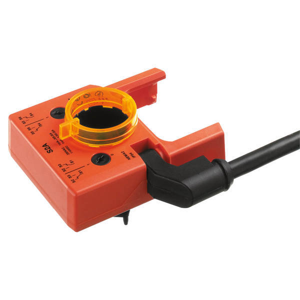
- Protection class IEC/EN
- II reinforced insulation
- Protection class UL
- II reinforced insulation
- Degree of protection IEC/EN
- IP54
- Degree of Protection
- IP54
- Material short text
- Add. switch 2 switch
- Actuator family
- Electronic Accessory
- Introductory text
- two switches (SPDT) Adjustable switching points
- Accessories title
- Auxiliary switch
- Accessories text
- Auxiliary switch add-on 1mA...3 (0.5) A, AC 250 V Adjustable switching point 0...100 %
- Accessories, miscellaneous
- 1mA...3 (0.5) A, AC 250 V|Adjustable switching point 0...100 %
- Accessories use
- add-on
- Mounting instruction
- https://www.belimo.com/pim/mam/europe/technical-documentation/Installation instruction/70153-00001_S..A_P..A.pdf
- Product family
- Accessory
- NA Product type
- ZE - Accessory electronic
- Structure Level1
- Actuators
- Structure Level2
- Accessories
- Ambient temperature
- -22...122°F [-30...50°C]
- Non-operating temperature
- -40...176°F [-40...80°C]
- Ambient humidity
- max. 95% r.H. non-condensing
- Maintenance
- maintenance free
- Auxiliary switch
- 2 x SPDT, adjustable 0...100%
- Auxiliary switch note
- adjustable 0...100%
- Connection auxiliary switch
- cable 1 m, 6 x 0.75 mm²
- Cable length auxiliary switch
- 1 m
- Cable cross-section auxiliary switch
- 0.75 mm²
- Number of strands auxiliary switch
- 6
- Clamping range damper spindle
- DIM_EU_S2A_1.eps
- Application
- The auxiliary switch unit is used for signaling the position or for exercising switching functions in any given angle setting.
- Connection
- cable
- Connection Cable
- YES
- Accessory type
- Electrical accessory
- Non-Spring
- GMB(X)|AMB(X)|NMB(X)|LMB(X)|LR|ARB(X)|GRB(X)|DRB(X)
- Electronic fail-safe
- DKRB(X)|NKQB(X)
- Agency Listing
- cULus acc. to UL60730-1, CE according to 73/23/EEC
- Mode of operation
- A carrier plate uses adaption to make a positive fit on the spindle clamp (damper actuators) or on the position indication (rotary actuators) and transfers the position directly to the switching cams of the micro switches. Switching points can be freely selected with an adjustment dial. The current switch position can be read off at any time.
- Direct mounting
- The auxiliary switches are attached directly by the spindle clamp (damper actuators) or on the position indication (rotary actuators). The guiding grooves between the housing and the switch ensure a tightly sealing fit.
- Safety notes
- The device must not be used outside the specified field of application, especially not in aircraft or in any other airborne means of transport. Only authorised specialists may carry out installation. All applicable legal or institutional installation regulations must be complied during installation. The device may only be opened at the manufacturer's site. It does not contain any parts that can be replaced or repaired by the user. Cables must not be removed from the device. The device contains electrical and electronic components and must not be disposed of as household refuse. All locally valid regulations and requirements must be observed.
Datasheet Download: Datasheet
Installation instructions Download: Installation instructions

Need Help?
Call one of our experts 1-888-423-2525
Monday-Friday EST 6:00am - 4:00pm


